REAR BRAKES
brake pads: REMOVAL
- Position vehicle onto lift.
- Remove rear wheels.
- Loosen lower retaining screw between brake caliper and mount.
- Turn brake caliper upwards, and remove pads from brake holder.
Brake pads: ASSEMBLY
- Correctly position brake pads onto brake holder.
- Retract piston using a suitable tool.
- Turn brake caliper downwards.
- Tighten brake caliper to mount retaining bolt to a torque of 26.5 Nm.
- Proceed to hydraulic system filling and bleeding.
Brake Discs: REMOVAL
- Position vehicle onto lift.
- Remove rear wheels.
- Remove union bolt and seal.
- Remove the 2 bolts and brake caliper from mount. (A)
- Remove the 2 bolts and mount from brake caliper. (B)
- Mark disc and axial hub.
- Remove disc from hub.
- Clean hub surface of rust and dirt.
brake discs: ASSEMBLY
- Fit brake caliper mount with the 2 bolts, and tighten to a torque of 88 Nm. (C)
- Tighten brake caliper to mount retaining screws to a torque of 34 Nm.
- Proceed to hydraulic system filling and bleeding.

WARNING: When retracting the piston into the caliper housing, brake fluid is pushed into the reservoir. When the caliper moves back, ensure that caliper piston is supported. Make sure that brake pad contact points are clean and free from any contamination.
PARKING BRAKE
BRAKE SHOES
brake shoes: REmOVAL
- Remove the 2 bolts and mount from cylinder.
- Remove brake shoe adjustment hole cap from
rear brake disc. - Mark disc and hub.
- Release parking brake.
- Turn brake shoe adjuster until disc turns freely,
then remove disc. - Using long nose pliers, remove the 2 tension
springs from brake shoe.
brake shoes: TENSION SPRING REMOVAL
- Disconnect parking brake cable.
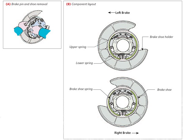
- Press brake shoe spring to remove (A) pin, spring
and brake shoe. - Disconnect parking brake cable from brake shoe
lever.
brake shoes: ASSEMBLY
- Apply high-temperature grease onto brake shoes
block plate mating surfaces. - Connect parking brake cable to brake shoe lever.
- Fit brake shoe complete with spring and pin.
- Apply high-temperature grease onto a section of
brake shoe adjuster screw. - Using long nose pliers, install tension spring.
- Apply high-temperature grease onto reaction rod
and brake shoe tension spring mating surfaces. - Using long nose pliers, fi t the 2 tension springs
onto brake shoe. - Refer to the picture below (B) to check for all
parts correct installation. - Align reference marks and fit brake disc.
- Fit brake disc and adjust parking brake.
WARNING: Brake fluid is hygroscopic, and it should be changed at regular intervals. Do not use fluid which does not comply with the specifications indicated in the table. Take care not to let fluid accidentally drop onto painted, rubber, plastic and mechanical parts.
ADJUSTMENT PROCEDURE
- Pull lever upwards and count 6 to 8 clicks.
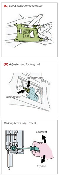
- Using a screwdriver, disconnect the 4 fixings.
- Disconnect connector and (C) remove rear
console upper panel. - Loosen (D) locking cable and adjuster nuts.
- Remove rear wheels.
- Remove the stopper, and turn adjuster to widen
brake shoe until disc is locked. - Turn brake shoe adjuster until it contracts where
disc can rotate freely. - Check that brake shoe does not create any friction
onto brakes. - Turn cable adjuster nut until reaching lever correct
travel. - Tighten locking nut to a torque of 6 Nm.
- Pull parking brake lever 3 to 4 times, and check
its travel. - Make sure that, when the parking brake lever is
pulled, brake warning light comes on upon the first click.
HYDRAULIC CIRCUIT
SYSTEM FILLING AND BLEEDING
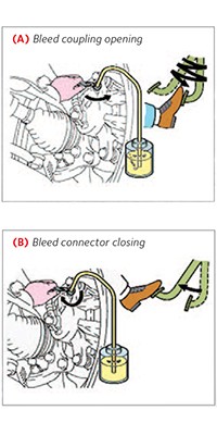
- Connect vinyl pipe to bleed cap.
- Press brake pedal several times, (A) then loosen
bleeder cap with the pedal pressed. - When fluid stops flowing out, tighten bleeder cap;
then (B) release brake pedal. - Once the bleeding operations have been completed,
carry out a road test where at least one
instance of ABS braking occurs.
Bleeding sequence
- left hand front brake caliper
- right hand front brake caliper
- left hand rear brake caliper
- right hand rear brake caliper
| BRAKE FLUID | ||
|---|---|---|
| Product | DOT 4 SAE J1703 | |
| Capacity | 1.0 litre | |
| Maintenance intervals | Replacement and bleeding every 2 years | |
| BRAKE FLUID DOT4 | ||
| FBX050 | 500 ml | 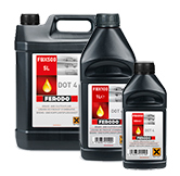 |
| FBX100 | 1 lt | |
| FBX500 | 5 lt | |
| FBX2000 | 20 lt | |
| Brake pads | FDB1892 | |
| Length (mm) | 96.6 | 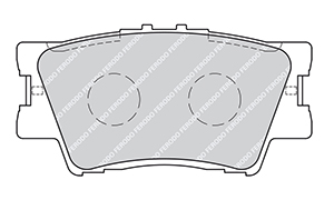 |
| Height (mm) | 49.50 | |
| Thickness (mm)* | 15.50 | |
| Thickness min (mm)* | 7.50 | |
| Discs | DDF1846 | |
| Diameter (mm) | 4281.00 | 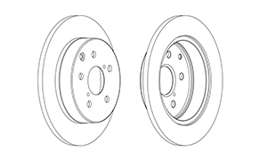 |
| Thickness (mm) | 12.00 Min. | |
| Thickness (mm) | 10.50 | |
| Parking brake shoes | FSB4035 | |
| Diameter (mm) | 4170.00 | 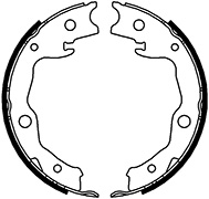 |
| Width (mm) | 432.00 | |