REAR/PARKING BRAKES
WARNING: Before attempting to work on the Passat Rear Brake System, it is essential to have the Diagnostic Software Interface, and a battery charger available (in addition to the usual workshop tools.)
The Passat is equipped with an Electromechanical Park Brake System, which is integrated into the rear brake calipers. It is therefore a requirement of the system that the diagnostic system is used to retract the pistons into the caliper housing.
The battery charger should be connected to the battery prior to starting any procedure on the vehicle using the diagnostic equipment. This will avoid any voltage fluctuation to the ECU and/or other control systems.
This model is fitted with an electromechanical parking brake.
Rear calipers are fitted with two motors controlling parking brake operation.
Note: Parking brake adjustment can only be carried out with a diagnostic tool, by following the repositioning procedure.
Rear/parking brakes: ReMOVAL
- Position vehicle onto lift.
- Remove rear wheels.
- Retract the pistons using the diagnostic system and then loosen the caliper slide pins.
- Remove the calipers and the brake pads.
- The caliper must be properly cleaned of all brake residue, especially on all moving surfaces.
- Slide pins must be cleaned and lightly lubricated with a high temperature molybdenum grease.
Rear/parking brakes: REPLACEMENT
- Push the caliper pistons to the full home position.
Note: Prior to returning the piston into the cylinder, draw out some of the brake fluid from the reservoir. If the reservoir is full, the brake fluid could overflow, causing damage.
- Fit brake pads to the brake hanger (arrows 1).
- Make sure that brake pads are properly positioned in their retaining plates (arrows 2).
Note: If brake pads have an adhesive surface, make sure they do not adhere to the caliper before they reach their correct position.
- Tighten the brake fluid hose coupling to caliper to a torque of 14 Nm.
- Secure the brake caliper, tightening the slide pins to a torque of 35 Nm.
- Check brake fluid level and top up when necessary.
Warning: After replacing the brake pads, fully depress the brake pedal several times to reposition the pistons in the calipers.
PARK BRAKE RESETTING
- Using the diagnostic system, reset the park brake motor pistons to their home position.
Note: Prior to returning the piston into the cylinder, draw out some of the brake fluid from the reservoir. If the reservoir is full, the brake fluid could overflow, causing damage.
- Connect the diagnostic tool to the vehicle and select the parking brake function.
- Reposition the pistons.
Warning: Piston repositioning using the diagnostic tool alone is insufficient. Press the piston fully home retracting the linkage by means of its presser (X) (see figure page 3).
BRAKE DISCs
brake discs: REMOVAL
- Remove the caliper frame by loosening the mounting bolts, to provide access to the brake disc.
- Loosen the locating screw and remove the discs and brake pads.
- Clean the caliper of all brake residue, especially on all moving surfaces.
Note: Do not try to force the brake discs off the wheel hub: in case of resistance use a rust-removing product.
brake discs: REPLACEMENT
- Position brake disc onto hub ensuring mating surfaces are clean.
- Tighten the locating screw to a torque of 4 Nm.
- Fit brake pads as per brake pad fitment section (page 1).
OPERATIONAL PRECAUTIONS
Brake fluid is hygroscopic, and it should be changed at regular intervals. Do not use fluid which does not comply with the specifications indicated in the table. Take care not to let fluid accidentally drop onto painted, rubber, plastic and mechanical parts.
HYDRAULIC CIRCUIT
BRAKE CALIPER BLEEDING
Note: Operation to be performed in case of caliper removal with cylinder overhaul.
- Loosen the bleed screw and, using a catch reservoir,
fill with brake fluid until it comes out air-free from the threaded hole at the end of the brake hose. - Tighten the bleed screw.
BRAKE MASTER CYLINDER LEAK CHECK
- Loosen and remove the bleed screw from one of the front calipers.
- Connect a pressure gauge to the component.
- Apply brake pressure until a 50 bars overpressure is reached.
- During the test (min. 45 sec), the pressure must not decrease by more than 4 bars; if the decrease is greater, replace the brake master cylinder.
PRELIMINARY BLEEDING
Bleeding sequence
- simultaneously bleed front brake left and right caliper
- simultaneously bleed rear brake left and right caliper
- Connect the supply and pressure bleeding device to the system.
- Leave the bleed screws loosened and keep the catch reservoir hoses in place until the brake fluid comes out air-free.
- Finally bleed the hydraulic unit again by selecting the specific program on the diagnosis tool.
REGULAR BLEEDING
- Connect the supply and pressure bleeding device to the system.
- Loosen bleed screws following the required sequence and bleed brake calipers.
- Connect an adequate flexible hose to the bleed screw. Make sure the hose is not bent to prevent air from entering the brake system.
- Leave the brake caliper bleed screw loosened and keep the catch reservoir hose in place until the brake fluid comes out air-free.
FINAL BLEEDING
Note: This operation requires two operators.
- Press brake pedal vigourously and keep it pressed.
- Loosen brake caliper bleed screw.
- Press brake pedal fully down.
- Tighten the bleed screw while keeping the pedal depressed.
- Release the brake pedal slowly.
- Operation to be performed 5 times for each brake caliper.
- left front caliper
- ight front caliper
- left rear caliper
- right rear caliper
- Once the bleeding operations have been completed, carry out a road test where at least one instance of ABS braking occurs.
| BRAKE FLUID | |
|---|---|
| Capacity | 1.0 litre |
| Product | DOT4 |
| Maintenance intervals | Change and bleed every 2 years |
| DOT4 BRAKE FLUID | ||
|---|---|---|
| FBX050 | 500 ml |  |
| FBX100 | 1 lt | |
| FBX500 | 5 lt | |
| FBX2000 | 20 lt | |
| FERODO PART NOS. | ||
|---|---|---|
 |
|
|
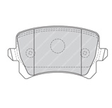
| Brake Pads | FDB1636 | FDB4192 |
| Size | 16" rims | 17" rims |
| Disc series No. | DDF1306 | DDF1503 |
| Disc diameter (mm) | 286 | 310 |
| Disc thickness (mm) | 12 | 22 |
| Disc wear limit (mm) | 8 | 18 |
| Brake pad series No. | FDB1636 | FDB4192 |
| Brake pad height (mm) | 55.5 | 56.2 |
| Brake pad width (mm) | 105.0 | 105.3 |
| Brake pad thickness (mm) | 16.9 | 16.8 |
| Pad wear limit (mm) | 7.0 | 7.0 |
| Caliper | TRW | TRW |
| Piston diameter (mm) | 38 | 41 |